Introduction
Ever wanted to add a touch of retro-futuristic flair to your DIY projects with a mesmerizing light source? Building a Larson scanner using the innovative SV2 PCB printer might be just the thing. Not only is this project a nod to classic sci-fi aesthetics, but it’s also a fantastic way to explore modern PCB prototyping techniques.
What is a Larson Scanner?
A Larson scanner is a dynamic lighting effect where LEDs light up in a sequence, creating a back-and-forth motion that mimics the scanning eye of iconic robots like the Cylons from Battlestar Galactica or KITT from Knight Rider. Named after Glen A. Larson, the creator of these shows, this effect adds a captivating, animated touch to any project.
Designing the Circuit Board
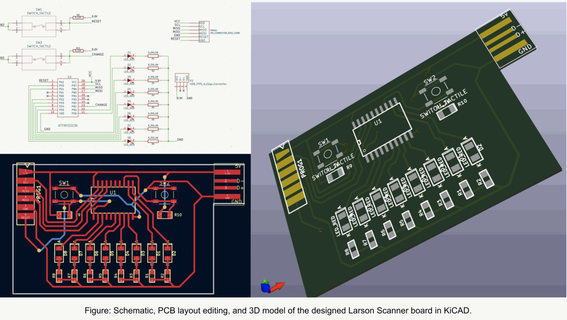
Design time! We crafted our circuit using KiCad and exported the files in the trusty Gerber RS-274X format. At the heart of our board is an ATtiny chip, perfectly capable of driving a bunch of LEDs, resistors, and tactile switches. Powering it is as easy as plugging in a USB cable. For programming, we’ve thoughtfully included edge connectors—you can even use crocodile clips to access the SDA, SCL, RESET, VCC, and GND lines. How convenient is that? The board itself is a sleek two-layer design printed on FR4 substrate, inheriting all the classic properties you’d expect from this material.
But hey, let’s not get too deep into the design weeds. After all, the real star of the show here is the PCB prototyping process!
If you are working with raw FR4 material, you can use a range of effective board-cutting tools suitable for different levels of complexity, from CNC routers to manual hand-cutters. For this particular project, manual board cutters are highly efficient, typically completing the task in just a minute or two. It’s important to note that we have deliberately excluded a CNC cutting head from our machine design because the dust produced from machining raw FR4 can be hazardous. Moreover, incorporating subtractive processes would contradict the principles of additive manufacturing that underpin 3D printing technology.
Pick and Place
The subsequent step involves the pick-and-place process for component assembly. The SV2 printer is equipped with another specialized interchangeable head that uses vacuum tips. This configuration enables precise and efficient picking of components from cut reels, which are placed on designated trays within the machine.

Final Results
With all the steps completed, the final task is to upload your program to the ATtiny2313A microcontroller. Using the Arduino IDE simplifies this process significantly. Once you’ve uploaded the code, your Larson scanner is ready to showcase its mesmerizing LED sequence, bringing your project to life.


